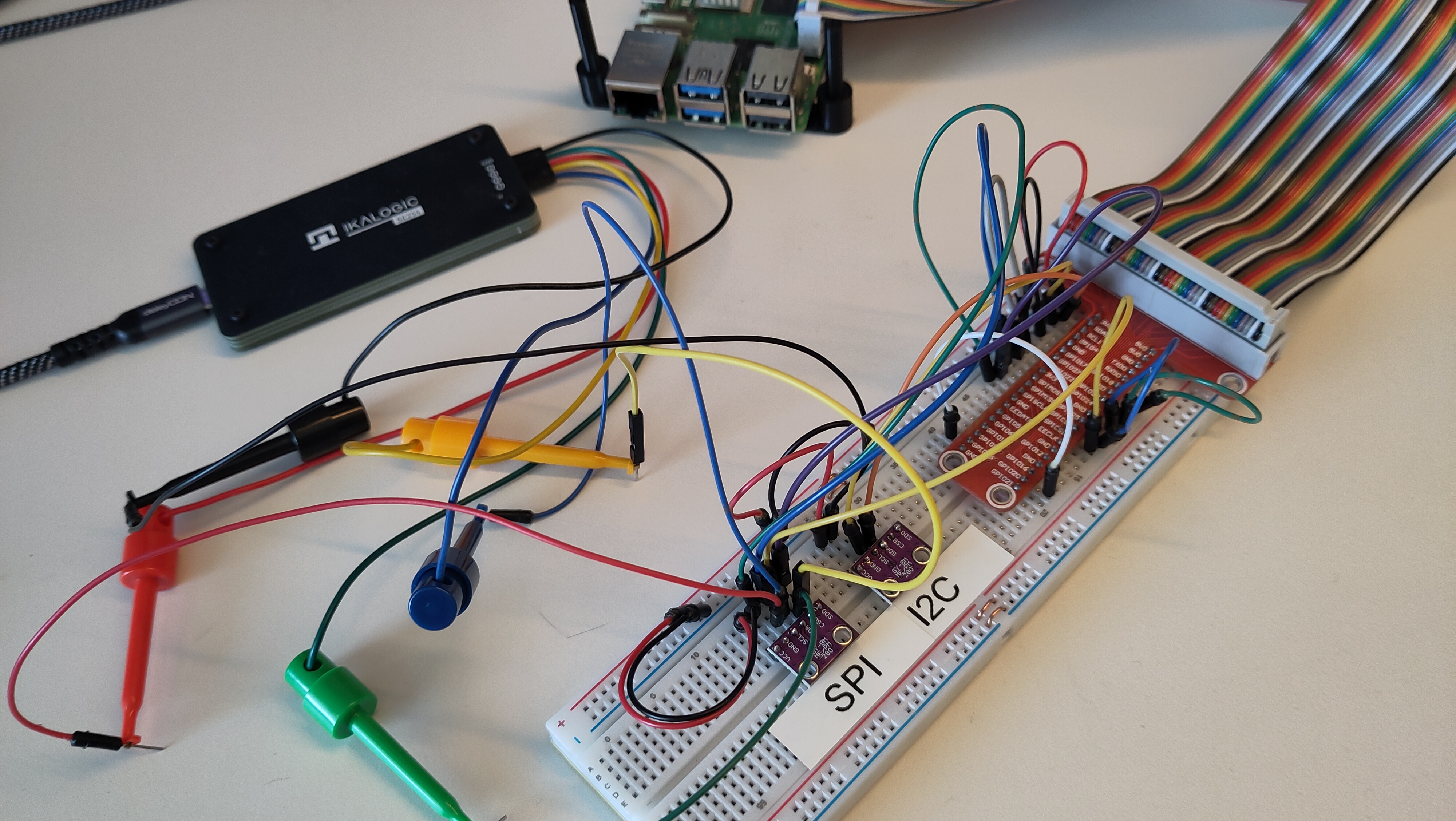
Ikalogic Analyser
When your Pi4J code passes the smoke tests but something still feels off, or when you’re implementing support for a new sensor and you’re not sure whether you’re sending the right commands, a logic analyser is the tool that lets you see exactly what is happening on the wire.
This page describes how to use the Ikalogic SE254 alongside the Pi4J Smoke Test setup to visualize and validate your GPIO signals.
Why a Logic Analyser?
Unit tests verify your Java code. The smoke tests verify that your code interacts correctly with real hardware. But neither of those tools tells you what data is physically being transmitted on the I2C, SPI, or PWM lines.
A logic analyser connects directly to the pins of your Raspberry Pi (or your peripheral device) and captures the electrical signals in real time. The Ikalogic software then decodes those signals and displays the actual bytes, commands, and timing in a readable format. This makes it straightforward to check:
- Did you send the correct initialisation command to your sensor?
- Is the data coming back from the sensor present on the bus, even if your Java code isn’t interpreting it correctly?
- Is your PWM duty cycle actually what you configured in code?
- Are your SPI MOSI and MISO lines behaving as expected?
The Ikalogic SE254
The SE254 is an affordable entry-level logic analyser with four logical channels, operating between 1.2V and 5V — which makes it compatible with the Raspberry Pi’s 3.3V logic level. It supports a wide range of protocol decoders including PWM, SPI, I2C, UART, and many more, all accessible through the ScanaStudio software.
Four channels is enough for the most common Pi4J I/O types:
- PWM: one channel for the signal, one for ground
- I2C: SDA + SCL (two channels), plus ground
- SPI: MOSI + MISO + SCLK + CS (four channels)
For more complex multi-bus scenarios, Ikalogic also offers analysers with more channels — but for typical Pi4J development work, four channels covers the majority of use cases.
At around 95 euros, the SE254 is an accessible option compared to professional bench analysers that can cost thousands of euros.
Connecting the Analyser
The SE254 connects to your Raspberry Pi via probe wires. When using it with the Pi4J Smoke Test wiring, you hook up the probe wires to the relevant T-cobbler pins alongside the existing jumper wires.
Always connect the black ground wire to a ground pin on your breadboard or T-cobbler before connecting any signal wires. The ScanaStudio software will colour-code your channels to match the physical probe cables.
Analyser Examples
Below you can find some examples of how to use the Ikalogic analyser to validate your Pi4J code. These were discussed in the video with Tom Aarts and Frank Delporte, starting at 12'59".
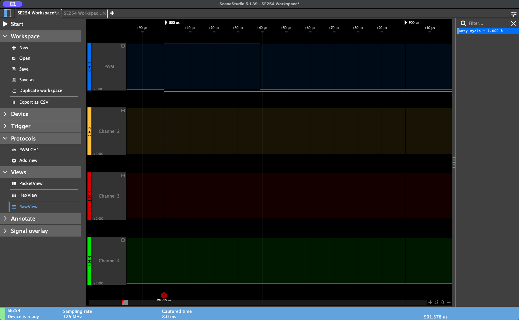
Validating PWM with the Smoke Test
In the Pi4J core code you can find an application that executes a set of “Smoke Tests”. The PWM test case configures a PWM signal on BCM 18 and connects it via a green jumper wire to BCM 23. The test runs the PWM for 10 seconds and counts the number of low-to-high transitions, expecting exactly 10 state changes at the default 50% duty cycle.
To visualise this with the Ikalogic analyser:
- Open ScanaStudio and create a new workspace
- Select your SE254 device
- Add a new protocol and choose PWM
- Connect the blue probe wire to the T-cobbler pin for BCM 18 (the PWM output pin)
- Connect the black ground wire to any ground row on the breadboard
- Set a trigger and start capturing
- Run your Pi4J smoke test (or your own Pi4J application)
At a 50% duty cycle with a slow flash rate, the analyser will capture the transition from low to high and display the waveform. To see multiple pulses clearly, reduce the duty cycle in your test code. For example, setting it to 1% produces a narrow pulse that is much easier to inspect visually, and the ScanaStudio display will confirm the configured duty cycle matches what is observed on the wire.
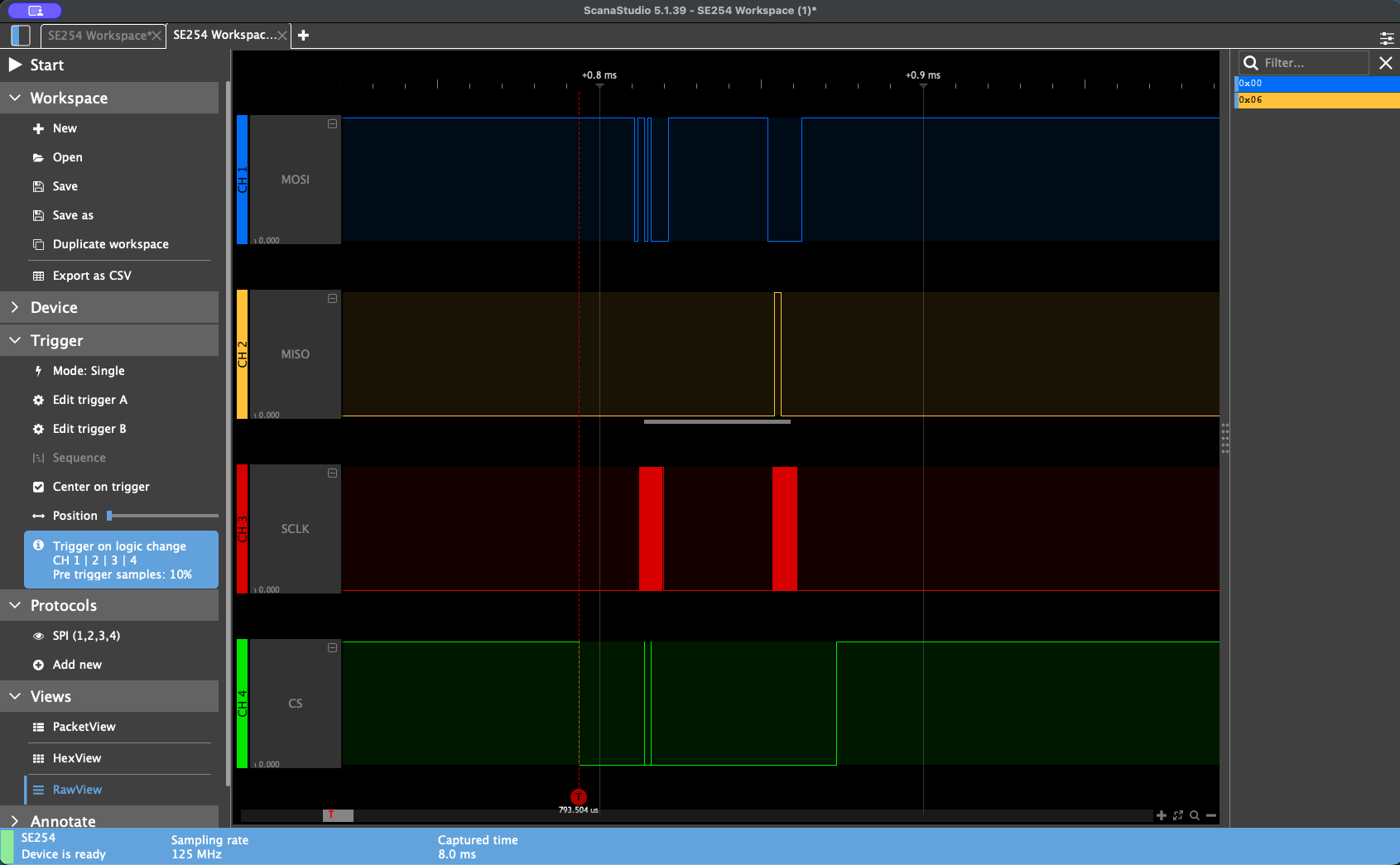
Validating SPI with the Smoke Test
The smoke test SPI test case communicates with a BME280 or BMP280 sensor wired as an SPI device. Once the test passes (confirming the sensor responds correctly), you can connect the Ikalogic analyser to inspect the actual bytes being exchanged.
For SPI analysis in ScanaStudio:
- Create a new workspace and add an SPI protocol
- Connect the four probe wires to the T-cobbler pins according to the smoke test wiring table:
- Blue (MOSI) → BCM 10 (Pin 19)
- Yellow (MISO) → BCM 9 (Pin 21)
- Green (SCLK) → BCM 11 (Pin 23)
- CS probe → BCM 8 (Pin 24)
- Black (GND) → any ground
- Set a trigger and start capturing
- Run the SPI smoke test
The ScanaStudio raw view will decode the captured traffic and display which bytes were sent over MOSI and which were received over MISO. This lets you cross-reference what your Java code sent against the sensor’s datasheet to confirm correctness — useful both for verifying existing functionality and for debugging new sensor drivers.
Combining Multiple Triggers
ScanaStudio supports running multiple protocol decoders simultaneously, so you can capture I2C traffic on two channels while also watching a GPIO state change on a third channel. This is particularly useful when debugging timing-sensitive interactions between different I/O types.