Smoke Test PCB
Running the Pi4J Smoke Test on a breadboard works, but it is fragile: every time the setup is rebuilt, a wire ends up in the wrong column, a jumper is not fully seated, or a sensor falls over. To make the smoke test fast and repeatable, and easy to hand to a contributor, we designed a dedicated PCB that turns the whole wiring table into a single board.
The full story of how the board was designed is described in this blog post and the accompanying video.
What is on the board
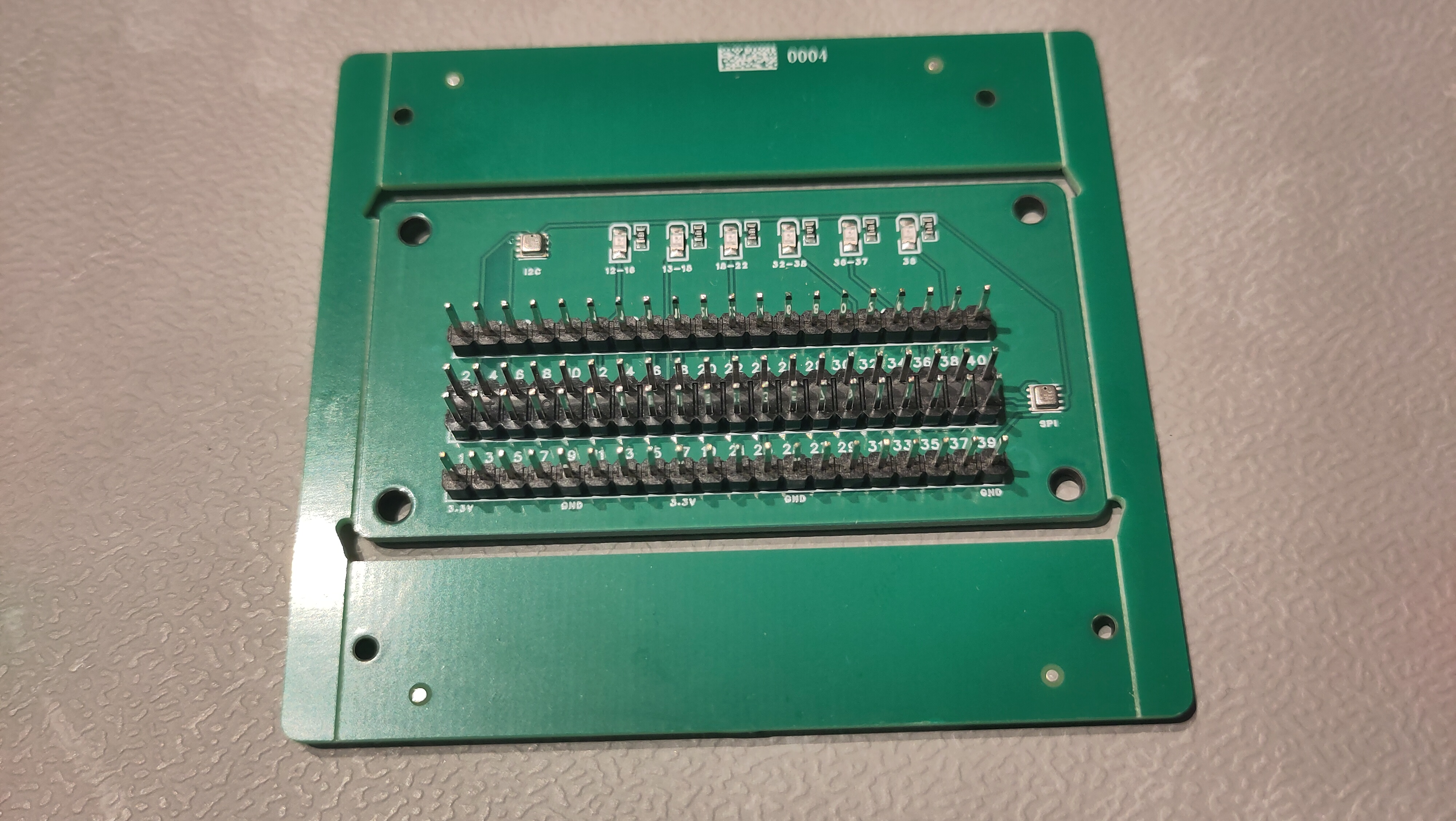
The board reproduces every connection from the smoke test wiring table:
- A 40-pin GPIO header across the middle, with the pin numbers printed on both rows, that connects directly to the Raspberry Pi GPIO header.
- A row of SMD resistors and LEDs above the header that light up while the GPIO-to-GPIO tests run, grouped by the pin ranges they cover (12-16, 13-15, 16-22, 32-36, 36-37, and 38). Each group maps to one of the test cases in the wiring table.
- An I2C connector on the left for the first BMP/BME280 sensor.
- An SPI connector on the right for the second BMP/BME280 sensor.
- Mounting holes in all four corners so the board can be fixed in place.
- Two extra 20-pin headers so a measuring instrument such as a logic analyser can easily be connected when something does not behave as expected.
The board was designed in EasyEDA Pro and manufactured by JLCPCB, which integrates directly with EasyEDA.
Order your own board
The design files are available in the pi4j-test/pcb directory of the Pi4J repository, so you can order the board yourself or modify the design.
The directory contains the following files:
- EasyEDA Pro project (
.epro) — the complete source design. Import it into EasyEDA Pro to open the schematic and PCB layout, modify the board, and order it directly through the built-in JLCPCB integration (or export Gerber files to order at another manufacturer). - BOM (
.xlsx) — the Bill of Materials listing every component, its quantity, and the matching LCSC part number, used when having the boards assembled (PCBA). - Pick & Place (
.xlsx) — the component positions and rotations used by the assembly machine. - Schematic (
.pdf) — a human-readable overview of all connections. - 3D model (
.step) — a 3D export of the board, for example to design an enclosure.
The minimum order quantity at JLCPCB is five boards. The 40-pin GPIO header is a through-hole part that is easy to solder yourself if it’s not available, so it does not need to be included in the assembly.
Feedback
If you have feedback on the design, or ideas for what should go on a future revision, open a discussion on the Pi4J GitHub or find us on Slack.